Pneumatic Control System Sketch
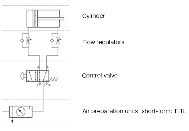
The General Design Of A Pneumatic System And Its Components
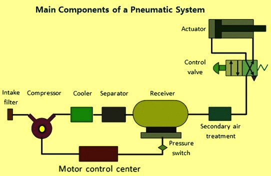
Basics Of Pneumatics And Pneumatic Systems Ispatguru
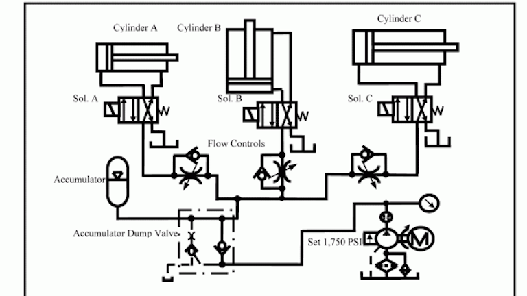
Chapter 5 Pneumatic And Hydraulic Systems Hydraulics Pneumatics
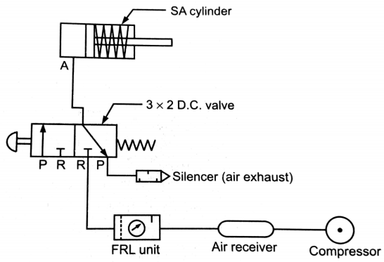
Explain Pneumatic Circuit For Speed Control Of Single Acting Cylinder With Neat Sketch Mechanical Engg Diploma Topicwise Notes And Solutions
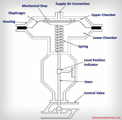
What Is A Pneumatic Actuator Instrumentationtools
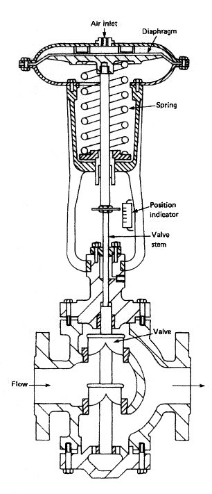
Pneumatic Control Valves For Marine Pneumatic Devices
Pneumatic circuit symbols representing these valves provide detailed information about the valve they represent.
Pneumatic control system sketch.

Block Diagram Of The Pneumatic Actuating System 1 Download Scientific Diagram
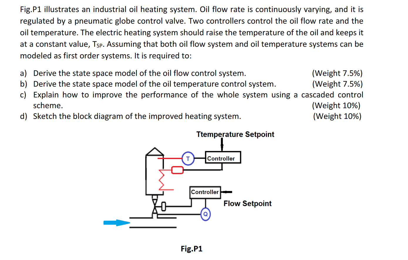
Fig P1 Illustrates An Industrial Oil Heating Syste Chegg Com
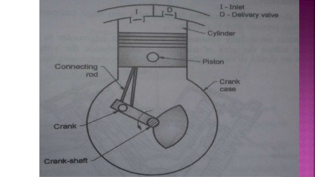
Pneumatic Control System
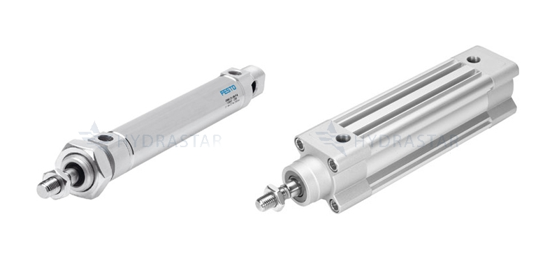
The Basic Components Of A Pneumatic System
Source : pinterest.com
