There are many styles of pneumatic actuators.
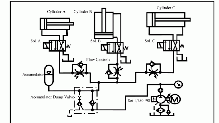
Pneumatic actuation system layout.
A rubber diaphragm separates the actuator housing into two air chambers.
They are ideal for quick opening and closing in both on off and control applications.
In general pneumatic systems are used for gripping and or moving operations in various industries.
The actuator positions a control valve by transmitting its motion through the stem.
However when a large amount of force is required to operate a valve for example the main steam system valves hydraulic actuators are normally used.
It operates by a combination of force created by air and spring force.
Pneumatic actuators come in many designs and sizes and include a variety of mounting methods internal features and options to provide a robust solution in industrial environments table 2.
Diaphragm cylinders rodless cylinders telescoping cylinders through rod cylinders etc.
It operates by a combination of force created by air and spring force.
For instance there are thousands of types sizes and variations of cylinders and valves from off the shelf versions to custom designs.
Piston type fluid accumulator general design.
They are economical and utilize compressed air readily available in most plants.
Hydraulic actuator design and operation pneumatic actuators are normally used to control processes requiring quick and accurate response as they do not require a large amount of motive force.
Quarter turn rotary actuators.
A safe pneumatic system design starts at the connection to a machine s air preparation hardware and continues to correctly pairing valves with cylinders.
In order to get a better overview we position the air preparation on the bottom and the actuators on the top of the drawing.
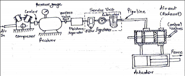
Air cylinders and motors are the actuators which are used to obtain the required movements of mechanical elements of pneumatic system.
A simplified pneumatic actuator diagram of a pneumatic actuator is shown in figure f1.
Pneumatic system design considerations.
The individual elements are represented by iso symbols which are connected with lines.
It s reliable economical and surprisingly easy to use.
Pneumatic actuation plays a major role in today s world of computerized automation.
A simplified diagram of a pneumatic actuator is shown in figure 1.
They display the route of the compressed air.
Pneumatic actuators are the most commonly used valve automation systems.
The actuator positions a control valve by transmitting its motion through the stem.
Pneumatic actuator design and operation.
The sketch exemplifies a pneumatic system at the machine level.